LUUM.IO
XS-108H - DATA SHEET#
Product Overview#
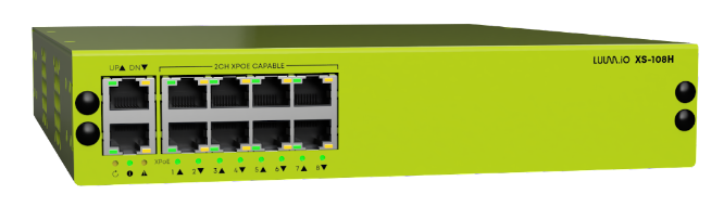
The XS-108H lighting controller represents a cutting-edge, high-performance solution, offering multiple channels for remote constant current/voltage LED driving. This controller stands out by providing 8 ports that can deliver controlled power in either IEEE standard (90W per port) or X-PoE (130W per port)1 configurations. Powered by a 48V-57V low-voltage DC input2, it ensures efficient and reliable operation within the lighting system, maintaining consistent and optimized power supply to the connected LED fixtures. With its advanced features and robust design, the XS-108H lighting controller sets the stage for exceptional performance and flexibility in contemporary lighting applications.
Specifications#
| XS-108H SPECIFICATIONS | |
|---|---|
| Dimensions | 219 mm x 254.7 mm x 44 mm (without mounting brackets) 8.6 in x 10 in x 1.7 in (without mounting brackets) |
| Weight | 1.9 kg (without mounting brackets) 4.2 lb (without mounting brackets) |
| Interfaces | (2) UP/DOWN Link RJ45 Ports (8) IEEE 802.3bt PoE++ / 2-CH X-PoE Lighting RJ45 Ports3 (1) DC Power Input Port2 (1) Aux. Dry Contact Input Port (2) Pin-Hole Operation/Reset Buttons |
| Power Input | 48VDC to 57VDC Input 100W - 1,000W Supply Recommended4 |
| Power Output (Per Channel) | Current: 1150mA Max. Voltage: 24VDC - 57VDC Power: 65W Max. (At 57VDC) |
| Maximum Power Consumption | 1,000W with all channels fully loaded at 100%5 |
| Power Metering Accuracy | >95% |
| Thermal Dissipation | 200 BTU/h |
| Environment | Operating Temp: 0°C to +40°C (32 to 104°F) Storage Temp: -20 to +40°C (-4 to +158°F) Humidity: 10% to 90% (non-condensing) |
| Certifications | UL 62368-1, UL 2108-1, CSA C22.2#62368-1 |
| Warranty | 5 Years |
| PORT SPECIFICATIONS | |
|---|---|
| Port Mode: X-PoE | Max. 130W/Port (at 57VDC) Constant Current/Voltage Output6 |
| Port Mode: IEEE PoE | Max. 90W IEEE 802.3bt PoE++/Port |
Power Output
Maximum output power is dependant upon the input voltage and the forward voltage of the connected light engine.
Front Panel#
The XS-108H front panel is shown below:
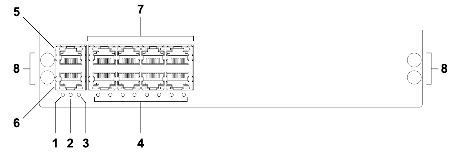
- System Reset Button
- System Status LED
- Programming Override Button7
- Port X-PoE Status LEDs
- Ethernet Uplink RJ45
- Unused
- IEEE/X-PoE Lighting Ports
- Coupling Bracket Mounting Holes
LED Descriptions#
| System Status LED (#2) | ||
|---|---|---|
| n/a | OFF | The system processor is not receiving adequate power |
| GREEN | ON | The unit is powered on and operating normally |
| GREEN | FLASHING | The unit is powered on and operating normally without an internet connection |
| ORANGE | ON | The unit is undergoing a system update |
| ORANGE | FLASHING | The unit is booting or rebooting |
| RED | ON | A system malfunction has been detected |
| RED | FLASHING | The programming override has been engaged |
| Port Status LEDs (#4) | ||
|---|---|---|
| WHITE | FLASHING | The port is not configured and is not providing power |
| WHITE | ON | The port is configured and is not providing power |
| GREEN | FLASHING | The port is not configured and is providing power |
| GREEN | ON | The port is configured and is providing power |
| ORANGE | ON | The port is providing power to an IEEE load |
| PURPLE | FLASHING | The port is in constant voltage discovery mode |
| RED | ON | An error has been detected on the port |
| RJ45 Connector LEDs | ||
|---|---|---|
| ORANGE (Left) | OFF | No network activity on the port |
| ORANGE (Left) | FLASHING | Network activity on the port |
| GREEN (Right) | OFF | No network connection is established on the port |
| GREEN (Right) | ON | A stable network connection is established on the port |
RJ45 LEDs
The LEDs on the RJ54 ports will only function for the uplink port.
Button Operation#
| Reset Button (#1) | ||
|---|---|---|
| PRESS | 2 TIMES | Restart the system processes |
| PRESS | 5 TIMES | Restart the unit |
| PRESS | 7 TIMES | Reset network settings |
| PRESS | 10 TIMES | Factory default all settings |
Rear Panel#
The XS-108H rear panel is shown below:
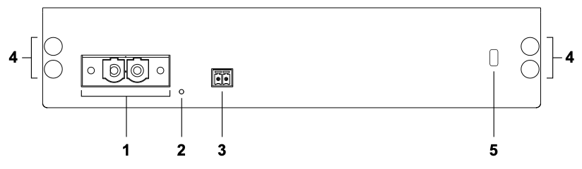
- Power Input (48VDC to 57VDC)
- System Power LED
- Programming Override Input (dry contact closure)
- Coupling Bracket Mounting Holes
LED Description#
| System Power LED (#2) | ||
|---|---|---|
| n/a | OFF | The unit is not receiving adequate power |
| GREEN | ON | The unit is powered on and operating normally |
| RED | ON | A system malfunction has been detected |
Override Input Description#
Engaging (or disengaging, based on the configuration) the input will activate the programming override. If the input remains deactivated for longer than 5 seconds, the override will be disengaged. By default, when the programming override is activated, all loads will be set to 100%. Once the override is disengaged, the loads will revert to their previous states. This default behavior can be customized in the configuration options:
-
Activate on Close:
- Engages the programming override when the input circuit is closed.
- Disengages the override if the input remains open for more than 5 seconds.
-
Activate on Open:
- Engages the programming override when the input circuit is opened.
- Disengages the override if the input remains closed for more than 5 seconds.
-
Override Level Settings for Each Channel:
- Each channel can have individual override level settings, allowing you to customize the load behavior during the programming override. Adjust the load percentage for each channel as needed.
Note
When connecting multiple X-PoE lighting controllers to the same programming override bus, it is critical that the override input polarity is consistent across all controllers.
For more information, see the programming override section of the install guide.
-
Maximum 130W per port with a 57V input, see D1.2 - Output Power Range. ↩
-
For more information, see D1.1 - Input Power Range. ↩↩
-
2 channels per port, 67W per channel with a 57V input. ↩
-
No Internal Power Supply. ↩
-
External Power Supply Must Be Rated For Total Lighting Load. ↩
-
(2) 67W (at 57VDC) Dimmable Channels/Port, Available On All Ports. ↩
-
The programming override button is currently not in use. Use the Override Input on the rear of the unit. ↩